Modbus Simulator
There are many different Modbus simulators available. The IOTech examples use the ModbusPal simulator as it is cross-platform and easy to use.
ModbusPal Prerequisites
ModbusPal requires Java and librxtx-java.
- Install Java
sudo apt install default-jre
- On Ubuntu,
librxtx-javais available as a software package and can be downloaded as follows:
sudo apt install librxtx-java
Install ModbusPal
Install ModbusPal using the link provided here.
Warning
This example runs with the specific version of ModbusPal provided above. Other versions of ModbusPal may not load the sample XMPP configuration file correctly.
Run ModbusPal
To run ModbusPal, navigate to the directory in which you extracted ModbusPal and enter the following command:
sudo java -jar ModbusPal.jar
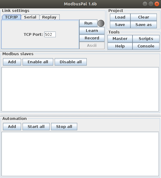
The ModbusPal will show up as illustrated below:
Configure ModbusPal
You can configure ModbusPal in either of the following ways - either using an XMPP configuration file or manually by using the user interface of ModbusPal.
XMPP Configuration File
ModbusPal can be configured with an XMPP file that defines the Modbus registers and any simulations.
To configure ModbusPal using the IOTech-supplied example XMPP file, complete the following steps:
-
Select the Load button. The Open dialog box displays.
-
Select /usr/share/edgexpert/examples/device-services/modbus/power-submeter/PowerSubmeter.xmpp
Note
If the XMPP file does not load, check that you are using the recommended version of ModbusPal.
-
Select the Start all button from the Automation options
- Select the Run button
Manual Configuration
To configure ModbusPal for use with the Modbus Device Service, you must do the following:
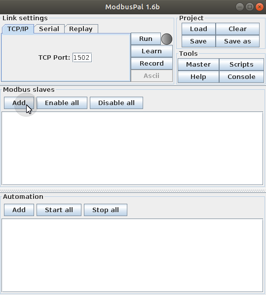
1. Configure the TCP Port
To configure the TCP port, set the TCP Port to 1502:

2. Configure the Modbus Slaves
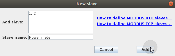
Select the Add button from the Modbus slave options, as illustrated below:
The New slave dialog box displays. Complete the following steps:
- Enter 1, 2 in the Add slave text box
- Enter Power meter in the Slave name text box
- Select the Add button, as illustrated below:
Note
If the XMPP file does not load, check that you are using the recommended version of ModbusPal
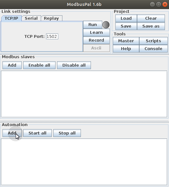
3. Add Automations
The following automation names are used in this example:
- Current1
- Energy1
- Power1
- Voltage1
To add automations, complete the following for each automation name:
-
Select the Add button from the Automations options
-
Enter the name of the new automation in the relevant text box
4. Configure Automations
The following automations are used in this example:
| Automation | Start Value | AutomationEnd Value | Duration | Current1 | 0.0 | 100.0 | 10.0 |
|---|---|---|---|
| Energy | 0.0 | 220.0 | 10.0 |
| Power1 | 0.0 | 1000.0 | 10.0 |
| Voltage1 | 0.0 | 110.0 | 10.0 |
To configure these automations, complete the following steps for each one:
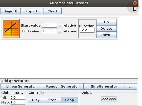
- Select the editor icon (eye) for the automation. The Automation dialog box displays
- Select LinearGenerator from the Add generators options towards the bottom of the window
- Enter the start value in the Start value text box
- Enter the end value in the End value text box
- Enter the duration in the Duration text box
-
Close the Automation dialog box:
5. Add the Registers
The following registers are used in the examples:
| Start Value | End Value | Name | Name Start Value | 9 | 9 | Current | 9 |
|---|---|---|---|
| 4001 | 4017 | Energy | 4001 |
| 4001 | 4017 | Power | 4003 |
| 4001 | 4017 | Voltage | 4017 |
| 4603 | 4609 | DemandWindowSize | 4603 |
| 4603 | 4609 | LineFrequency | 4609 |
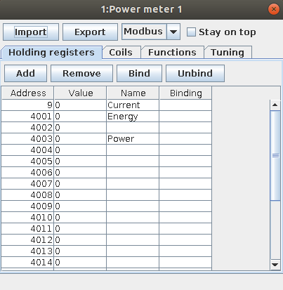
To add registers, complete the following steps:
- Select the editor icon (eye) for the Power meter slave
- Select the Add button. The Add registers dialog box displays
- Enter the start value in the From text box
- Enter the end value in the To text box
- Select the Add button
- Repeat steps 3 to 5 for each start and end value
- Add the name in the row containing the relevant start value
When all information has been added, the Add registers dialog box will look similar to the following:
6. Bind the Registers
The following bindings are used in this example:
| Registers to Select (Inclusive) | Automationm | Binding | 9 | Current1 | Binding_SINT16 |
|---|---|---|
| 4001 to 4002 | Energy1 | Binding_FLOAT32 |
| 4003 to 4016 | Power1 | Binding_SINT16 |
| 4017 | Voltage1 | Binding_SINT16 |
To bind registers, complete the following steps for each register:
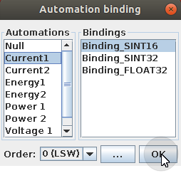
-
Select the rows containing the registers that you wish to bind
-
Select the Bind button. The Automation binding dialog box displays
-
Select the automation from the Automations list
-
Select the binding from the Bindings list
-
Select OK:
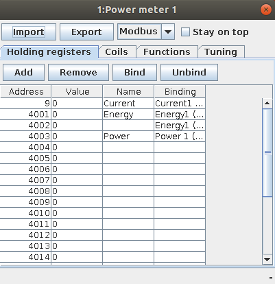
-
Close the Add registers dialog box. When all information has been added, the Add registers dialog box looks similar to the following:
6. Running the Simulation
-
Select the Start all button from the Automation options
-
Select the Run button